SDV Electronics and Embedded Systems
Electronics (Electric motor)
This car works with 48V. 4 12V batteries power this car, these 4 batteries are connected in series in order to provide 48V. Next in this document all components that are part of the electromotive part of the vehicle will be explained, and some specs or thips to operate and repair this vehicle will be given.
Components
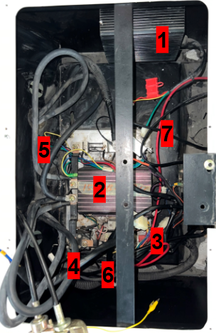
Car electronics big picture.
Number |
Name |
Notes |
|---|---|---|
1 |
Voltage converter input: 36V-80V Output: 12V 30A |
Doesn’t work it may have gotten bad with a failed test |
2 |
Curtis 1204M motor controller |
Works well Yellow-switch Green and blue-speedmodulation through a change in current given by the electric pedal Datasheet: https://cdn.curtisinstruments.com/products/ manuals/MSeries_manual_en.pdf |
3 |
Positive terminal that carries +48V |
|
4 |
Solenoid |
Activated by 1 cable located in one of the sidewalls, this lets all power pass to the controller instantly when the pedal is pressed, this pedal sends a signal by a microswitch |
5 |
Low current cables to modulate controller output |
Yellow-switch Green and blue- speed modulation through a change in current given by the electric pedal |
6 |
250A fuse |
For protection |
7 |
Gray box for charging protection box |
This box works as a converter or computer to be able to convert high current signals delivered by the pedals or other components into a lower current signal that can be processed and used by the controller |
The acceleration pedal is a potentiometer that varies its resistance depending on the position of itself, a micro switch is located just where the pedal starts moving, this activates the solenoid and starts the motor controller
The car key was not delivered when adopting this car project, currently in order to start the car, the 2 wires connected to the key switch must be interconnected. This key switch will be changed during last 2022 semestre to either a pushbutton or a selector switch in order to turn on the car in a safe way

This diagram shows the wiring of a curtis 1205M, the model present in this project vehicle is curtis 1204M, the only difference is that 1204m has no J4 input, it only has J1, J2, and J3.
The key switch will be replaced for a button or selector and the pedal microswitch activates the Solenoid which in the diagram is identified as “Main”. The 5k ohms throttle is the representation of the potentiometer that is located in the pedal, this will modulate speed and will deliver a low current to the controller through J2 and J3. The power wiring fuse has a limit of 250A
Electronics (Electronic accessories)
The car has an accessory set that includes:
2 normal and high light bulbs
2 turn light bulbs
2 fog light bulbs
wipers
6 back lights
dashboard with speedometer, voltmeter and ammeter
Most of these components need 12V given by a converter that turns 48V from the batteries and the car into 12v and 30A as output. The only component fed by 48V is the dashboard, the reason for this is that the voltmeter measures voltage and needs the 48V in order to sense that our battery is full and everything is working properly.
Lights/turn lights connector
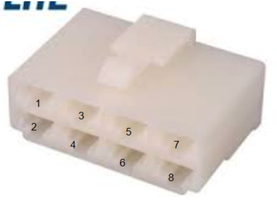
Pin |
Function |
A |
Cable |
|---|---|---|---|
1 |
Connected to the fog lights switch and it may activate the lower light bulbs when the switch is activated. did nothing |
Desconocido |
82 |
2 |
normal lights |
||
3 |
Right Turn Light |
||
4 |
Both lower light bulbs (fog lights) |
0.1A |
|
5 |
GND |
||
6 |
nothing |
||
7 |
Both lower lights |
0.1A |
|
8 |
Normal lights (both) |
0.7A |
Wipers connector
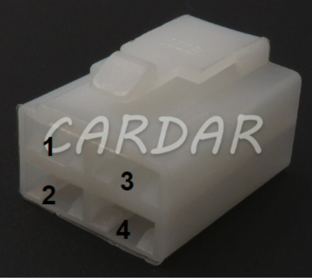
Pin |
Function |
Cable |
|---|---|---|
1 |
Unknown |
|
2 |
GND |
Black |
3 |
12V activator |
Green |
4 |
Both lower light bulbs (fog lights) |
Red |
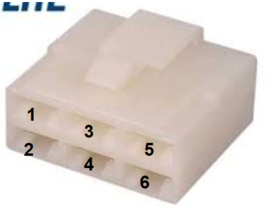
Pin |
Function |
Cable |
|---|---|---|
1 |
Speakers located in the car roof |
|
2 |
Speakers located in the car roof |
|
3 |
GND |
|
4 |
Claxon |
|
5 |
Unknown |
|
6 |
Speakers located in the car roof |
Battery connection (48V connecting 4 12v batteries in series)

STM32G431KB Configuration for CAN
The first step is to configure the bit timing parameters , they are required for determining the Nominal Baud Rate. In the experiment, we are using 500 (kbit/s) with an FDCAN 16Mhz clock configuration. We can use the following website for the experiments: http://www.bittiming.can-wiki.info/

We are going to use the Pre-scaler, Seg1 and Seg2.

Those values are entered in our STM32:

Now, we need to add the Basic Parameters for CAN communication, those signals are obtained with the following website: https://www.kvaser.com/support/calculators/bit-timing-calculator/

The result of the configuration will give us Data Time Seg1 , Data Time Seg2, Data Sync Jump Width. It is also important to mention that Sample Point (SP%) should be 87.5% to work properly.

For the final step, we entered those parameters to our STM32G431KB.

Embedded Modules
Embedded Modules
- Embedded Modules
- CAN Communication
- CAN STM32
- Common Module Subsystems
- Stepper-Based Modules
- Transmission Module
- Throttle Module
- Octocoupler SFH617A-1
- Mosfet WST2N7002A
- LTspice Tests
- Real-life Tests
- Curtis speed controller
- Digital Potentiometer
- Why A0 and A1 is connected to GND?
- Why VDD has decoupling capacitors?
- Why so many 0 resistors in Terminal A and B?
- Tests with Digital Pot X9c103s 10k and Pot5k
- Throttle module STM32 Programming
- References